Setting up the OpenGL Projection Matrix
 Last time we saw that modern OpenGL requires you to do matrix math. Moving,
rotating, or scaling an object in 3D space are all done by matrix
multiplication. The camera object works in exactly the same way, but to get
anything displayed on-screen we first need to properly initialize the
projection matrix. Next we can setup the camera (view matrix), and finally
transform our objects (model matrix). As we saw last time, this all comes
together in the vertex shader as:
gl_Position = projection * view * model * input;
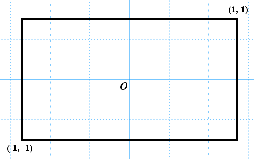
First off, what is a projection? A projection distorts a view so that it will fit onto the screen. For example, think of a movie projector: a light source illuminates a single frame of film, and a lens spreads the beam such that the image appears on a much larger movie screen. In other words, the projection transforms the frame to fit the screen. The frame coordinates are transformed to screen coordinates, but OpenGL does not directly work with screen coordinates; it uses normalized device coordinates. Normalized device coordinates run from -1 to 1, regardless of both screen resolution and aspect ratio. In a sense, the projection will contract the image, and OpenGL will stretch it again over the viewport so that the final result is a normal image, displayed on the screen.
So to render an image, we must map our modelview space to normalized device coordinates. Let’s first examine how that works for an orthographic projection. An orthographic projection ignores perspective, and is used for 2D and isometric projections.
Consider any point (x, y, z) in our viewing volume. Naturally x lies between left and right, and y lies between bottom and top, so we can write:
  left <= x <= right
bottom <= y <= top
  near <= z <= far
Let’s start with the first proposition. We can rearrange it so that x will fall between -1 and 1.
 0 <= x - l <= r - l
 0 <= (x - l) / (r - l) <= 1
 0 <= 2 ((x - l) / (r - l)) <= 2
-1 <= 2 ((x - l) / (r - l)) - 1 <= 1
The middle part rewrites to:
2 x / (r - l) - ((r + l) / (r - l))
In other words, the x scaling factor is 2 / (r - l), and the x offset
is given by - ((r + l) / (r - l)). You can write this in a transformation
matrix (column major notation):
w = r - l

2.0 / w    0    0    -(r + l) / w
0          1    0     0
0          0    1     0
0          0    0     1
If you write this out for all three x, y, and z, you get the full orthographic projection matrix (in column major notation):
w = r - l
h = t - b
d = f - n

2.0 / w    0          0          -(r + l) / w
0          2.0 / h    0          -(t + b) / h
0          0         -2.0 / d    -(f + n) / d
0          0          0          1
For 2D I like having a math-like coordinate system where the origin lies at the bottom left, positive Y-axis pointing up, meaning that left and bottom will be zero. Many old-time programmers are used to having the origin at the top left, positive Y-axis pointing down, as this corresponded with how display framebuffer memory was laid out. This was in the days before OpenGL however, and back then computer graphics was more about plotting pixels than transforming vertices.
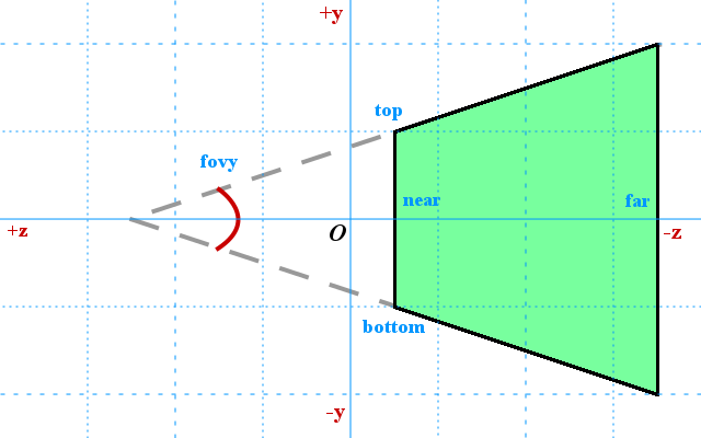
Things get a bit more complicated for 3D perspective projections, but the principle is the same. The projection acts like a virtual lens, distorting an image. A perspective projection creates the illusion of depth by showing distant objects smaller than objects that are close. This illusion is created by the viewing frustum, a trapezoid-like shape that distorts space. Let me be clear about this, it actually pushes objects out of shape to create the illusion of depth on a flat display screen.
The well-known (but deprecated) gluPerspective() function takes a vertical
viewing angle fovy and uses simple trigonometry to find the values for
left, right, bottom, and top:
radians = deg2rad(fovy) : fovy * Pi / 180.0
p = tan(radians * 0.5) * near
l = -p * aspect_ratio
r = p * aspect_ratio
b = -p
t = p
Note how this conveniently puts the origin of the coordinate system in the
center of the XY-plane of the viewing volume. These values we will plug into
our own version of glFrustum() to construct the perspective matrix, as
follows.
Perspective distortion is created by dividing by the z coordinate; a larger z coordinate results in smaller objects in the distance. This crunches objects, creating the illusion of depth. When you work out the math, this results in the perspective projection matrix (column major notation):
w = r - l
h = t - b
d = f - n

2.0 * n / w    0              (r + l) / w    0
0              2.0 * n / h    (t + b) / h    0
0              0             -(f + n) / d   -2.0 * f * n / d
0              0             -1              0
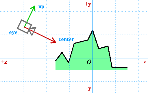
Once upon a time there was a convenient gluLookAt() function for setting
up the camera. You can aim the camera at a center position, and you must
pass an up vector: is the camera being held up straight, or is it rolling
on its side.
To get the camera matrix, we will first calculate three vectors:
vec3 f = normalize(center - eye)
vec3 s = normalize(cross(f, up))
vec3 u = cross(s, f)
Remember that the cross product is a vector that is perpendicular to two given vectors. So what we did here is defining the axis of the (possibly rotated) camera space.
This results in the following view matrix. Remember that the dot product is the cosine of the angle between the two given vectors; the adjacent divided by the hypotenuse. The dot products in this matrix reflect the position of the camera, while the other numbers represent its orientation.
 s0    s1    s2   -dot(s, eye)
 u0    u1    u2   -dot(u, eye)
-f0   -f1   -f2    dot(f, eye)
 0     0     0     1
I have tried to explain how you get the projection and view matrices.
Of course, you can ignore all this and just use the glm library; that’s
what it’s for. However, it’s good to know how it actually works.
My math skills aren’t as strong as used to be, but in principle all of this
stuff can be done by applying high school level math. It certainly took me
a while to get all the pluses and minuses correct. What can be confusing
is that OpenGL expects a (regular) right-handed coordinate system for
world space, but the projection transforms it to a left-handed system
by flipping the z coordinate. Therefore it is said that OpenGL uses a
left-handed system internally. Anyway, more thorough derivations can be found
at SongHo and Scratchapixel, both excellent sites that teach
professional-grade computer graphics. It’s complex matter though and
I would rate them at university level. If you want to learn more, those are
the places to look.
- OpenGL Projection Matrix at SongHo
- The Perspective and Orthographic Projection Matrix at Scratchapixel


